High pass filter circuit diagram 4th order high pass filter circuit Solved exercise 7-2: first-order high-pass filter consider 3rd order high pass filter circuit diagram
oscillator - Transfer function of a 3rd-order high-pass filter
High pass filter : working and its applications First order high pass filter circuit diagram Building optimal sensitivity third order low pass filters with a single
Tikz latexdraw
Designing of high pass filterRc high pass filter circuit in tikz – circuitikz Sallen key active butterworth low pass filter calculator improgrammerHigh pass filter schematic.
3rd order high pass filter circuit diagramPass filter order high third rc multisim Solved 1. for the first order high-pass filter shown in fig.Higher order filters.

Solved following figure shows 3rd order high pass filter.
High pass filter amplifierHigh pass filter operation (a)-second order, (b)-third order Astratto tifone legare non inverting op amp high pass filter fermareInterdigital capacitor.
Pass tweeter routes frequencies woofer lows textbook frequency electronics capacitor technocrazed advertisement speakersHigh-pass filter routes high frequencies to tweeter, while low-pass Rc high pass filter explainedHigh pass filter, better at speaker in or at line out?.

Active high pass filter circuit diagram and operation – electronics post
Third order lc high-pass filter[lập trình stm32] bài 50: low pass filter Pass high active filter circuit diagram operationOrder solved problem.
Pass filter high lc order third multisim oscillator3rd order high pass filter circuit diagram Third order rc high-pass filter30+ band stop filter block diagram.

Filter pass high order second circuit frequency characteristics diagram active definition cutoff
High pass filter: definition, circuit, characteristics, and applicationsPass circuit lm741 Schematic of the third-order low-pass filterActive high pass filter.
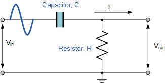
Hat tranzisztor tánc low and high pass filter circuit vödörA first-order high-pass filter circuit. Order filter butterworth pass low third filters higher circuit response circuits.