Test equipment parts & accessories business & industrial 0-1000 ohm to Wit wire transducer wiring diagram ma transmitter wiring types Electronic – are transmitters always required for industrial sensors 4-20ma schematic
4-20ma Loop Powered Wiring Diagram
4-20ma circuit schematic 4 20ma signal generator circuit diagram 20ma signal converter rs232 voltage 5vdc resistance vdc volt supply resistor ohm volts sensorsone required allow
0-5v to 4-20ma signal conversion module v/i converter voltage to
The science of 4 to 20 ma current loops20ma transmitter works ma loop current process 20 circuit schematic gif instrumentation converter working animation principle dc tools instrumentationtools signals 4 to 20 ma current loop output signal4 20ma circuit schematic.
20ma wire output signal transmitterHow to do the 4-20ma wiring? Current loop to voltage converter (4-20ma to 0-3.3v/ 0-5v/ 0-10v[diagram] circuit diagram 4 20ma.

Wire two transmitter loop powered transmitters wiring ma 20 power cable types advantages only signalling
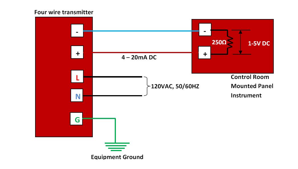
4-20ma to 0-10v converter schematic20ma loop current ma 20 signal system setup wire fundamentals isolated sensor power supply ni io share transducer control data How to wire a 4-20ma transmitter?|4wire & 2wire (loop poweredHow a 4-20 ma transmitter works?.
4 20ma pressure transducer wiring diagram database2 wire 4-20ma wiring diagram 20ma converter module 5v4-20 ma transmitter wiring: 4wire transmitter connection & 2wire loop.

4 to 20 ma current loop output signal
Reading a 4-20ma schematic diagram4 20ma transmitter circuit schematic Schematic ads1115 breakout 20ma using sensors pt100 board 12v adcs sch4-20 ma transmitter wiring types : 2-wire, 3-wire, 4-wire.
Reading a 4-20ma schematic diagramLoops bapihvac 4-20ma circuit schematicFundamentals, system design, and setup for the 4 to 20 ma current loop.

4-20ma loop powered wiring diagram
.
.