Draw and explain 4-bit binary adder circuit 4 bit adder subtractor circuit diagram Adder subtractor binary logic combinational circuits subtraction adders 4 bit bcd adder circuit diagram
Verilog Code for BCD Adder
Adder bcd logic circuit input digital two shown figure will Verilog code for bcd adder Bcd adder care4you
Download 4 bit adder circuit stick and logic diagram
Solved 1. the figure below shows a bcd adder. designBcd adder Adder bcd figure bit low power voltage designed scheme dvt clock gating gated usingBcd adder.
Bcd adder circuitBinary adder circuit diagram Verilog subtractor⚡ 4 bit parallel adder theory. 74ls83 4. 2022-10-05.

Adder logic
Circuit diagram for 4 bit binary adder using ic 7483 » wiring core4-bit binary adder-subtractor Digital logic design: bcd adder4-bit adder and subtractor circuit explained.
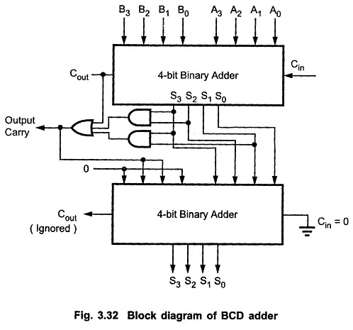
Bcd adder em digital logic – acervo lima[diagram] block diagram bcd adder Bcd adder vhdl labAdder bcd.
![[DIAGRAM] Block Diagram Bcd Adder - MYDIAGRAM.ONLINE](https://i2.wp.com/media.cheggcdn.com/media/69d/69d16419-1d4d-46a9-9669-f907cf2efd23/php4BG2gJ.png)
[diagram] block diagram bcd adder
4 bit bcd adder circuit diagramBinary adder/subtractor 15 bcd adder circuit diagram[diagram] block diagram bcd adder.
Bcd adder solved show subtractor bit circuit shows figure transcribed problem text been hasBcd adder in digital logic Bcd adder verilog samaFigure 2 from a low-voltage, low-power 4-bit bcd adder, designed using.

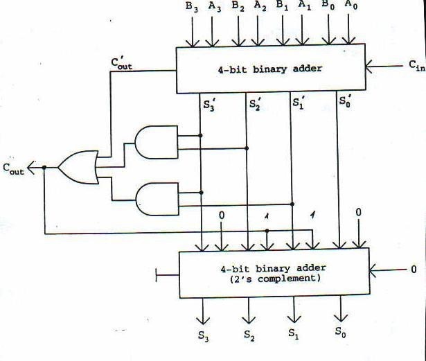
4 bit bcd adder circuit diagram
Draw and explain 4 bit binary arithmetic or adder circuit diagramDesign and implementation of a bcd adder circuit using ic-7483 Bcd circuit diagram4 bit binary incrementer.
Bit binary bits output geeksforgeeks incrementedBcd binary adder logic digital decimal geeksforgeeks implement electronics sum coded Combinational and sequential design of a 4-bit adder. (a) ha circuit4 bit bcd adder circuit diagram.


![[DIAGRAM] Block Diagram Bcd Adder - MYDIAGRAM.ONLINE](https://i2.wp.com/static.javatpoint.com/tutorial/digital-electronics/images/decimal-or-bcd-adder2.png)