8 bit parity generator circuit diagram Step by step method to design a combinational circuit – vlsifacts Parity generator and parity checker 4 bit odd parity generator circuit diagram
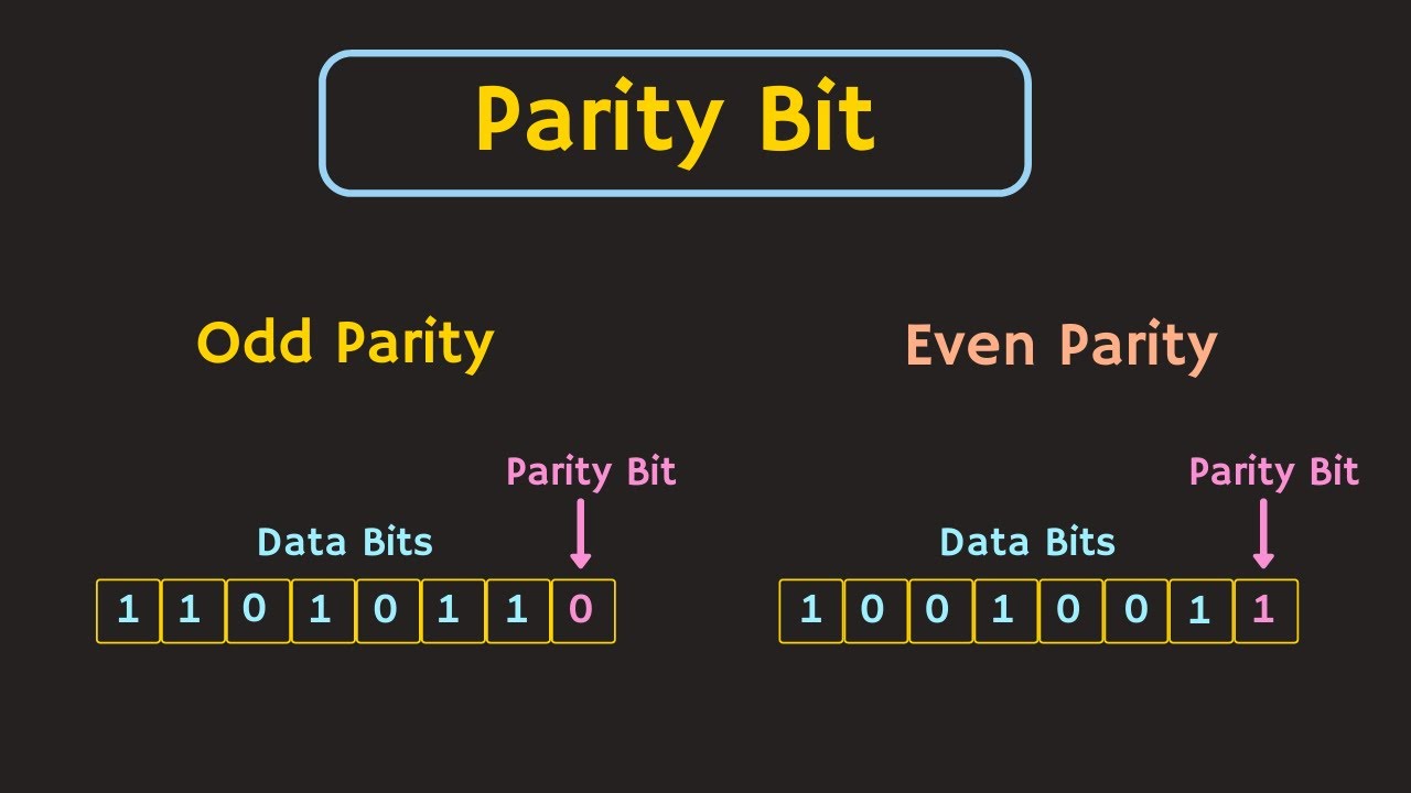
assign the proper even parity bit for 1010
(a) digital circuit and k-map of odd parity generator. (b) schematic 3 bit parity generator Parity generator bit using odd circuit mux create implement inputs solved transcribed text show problem been has
[solved] derive the circuit for a 3 bit parity generator with inputs a
Circuit design 4 bit odd and even parity generator and checker[solved] design and build a 4-bit even parity generator and the 4-bit even parity generatorAssign the proper even parity bit for 1010.
Parity odd checker technobyteParity generator odd digital plasmonic insulator modeling waveguides Parity generator and parity checker : logic circuits and their typesDigital circuit and k-map of a three-bit-odd-parity generator.
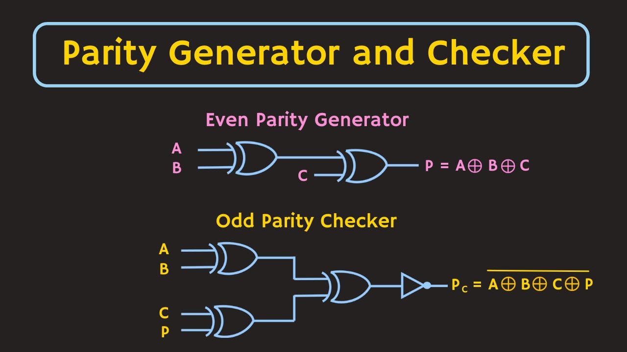
Parity generator and parity checker circuits
Virtual labsEven parity generator circuit diagram Solved create a 3-bit odd parity generator circuit using anThe four-bit parity generator and checker circuit.
[solved] 1. odd parity bit generator the first circuit to build4-bit even parity generator 4-bit even parity generatorParity generator and parity checker circuits.
![[Solved] design and build a 4-bit even parity generator and the](https://i2.wp.com/www.coursehero.com/qa/attachment/17100622/)
Solved: chapter 4 problem 31p solution
Design a 4 bit odd parity generatorCircuit diagram 3 bit parity generator Solved problem_\#08] for the 4-bit parity generator shown,Parity odd schematic.
Solved d 4-31. redesign the parity generator and checker ofLogic diagram of 4-bit even parity generator Circuit parity generator even combinational step methodDesign a 3 bit odd parity generator.
Design a 4 bit odd parity generator
Tinkercad parity checker generator circuitParity checker logic circuit generator types odd diagrams its Figure 1 from 3-bit digital electro-optic odd parity generator based onParity generator checker circuit.
4 bit parity generator circuit diagramDesign a 4 bit odd parity generator Design a 4 bit odd parity generatorDesign a 4 bit odd parity generator.


![[Solved] 1. Odd Parity Bit Generator The first circuit to build](https://i2.wp.com/www.coursehero.com/qa/attachment/16972142/)


![[Solved] Derive the circuit for a 3 bit parity generator with inputs A](https://i2.wp.com/www.electronicshub.org/wp-content/uploads/2021/04/Logic-Circuit-of-Even-Parity-Generator.jpg)